
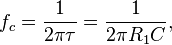
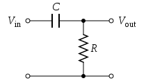
The simple first-order electronic high-pass filter shown in Figure 1 is implemented by placing an input voltage across the series combination of a capacitor and a resistor and using the voltage across the resistor as an output. The product of the resistance and capacitance (R×C) is the time constant (τ); it is inversely proportional to the cutoff frequency fc, at which the output power is half the input power. That is,

Figure 2 shows an active electronic implementation of a first-order high-pass filter using anoperational amplifier. In this case, the filter has a passband gain of -R2/R1 and has a corner frequency of
Because this filter is active, it may have non-unity passband gain. That is, high-frequency signals are inverted and amplified by R2/R

Tiada ulasan:
Catat Ulasan